PlaneView Laser Assembly
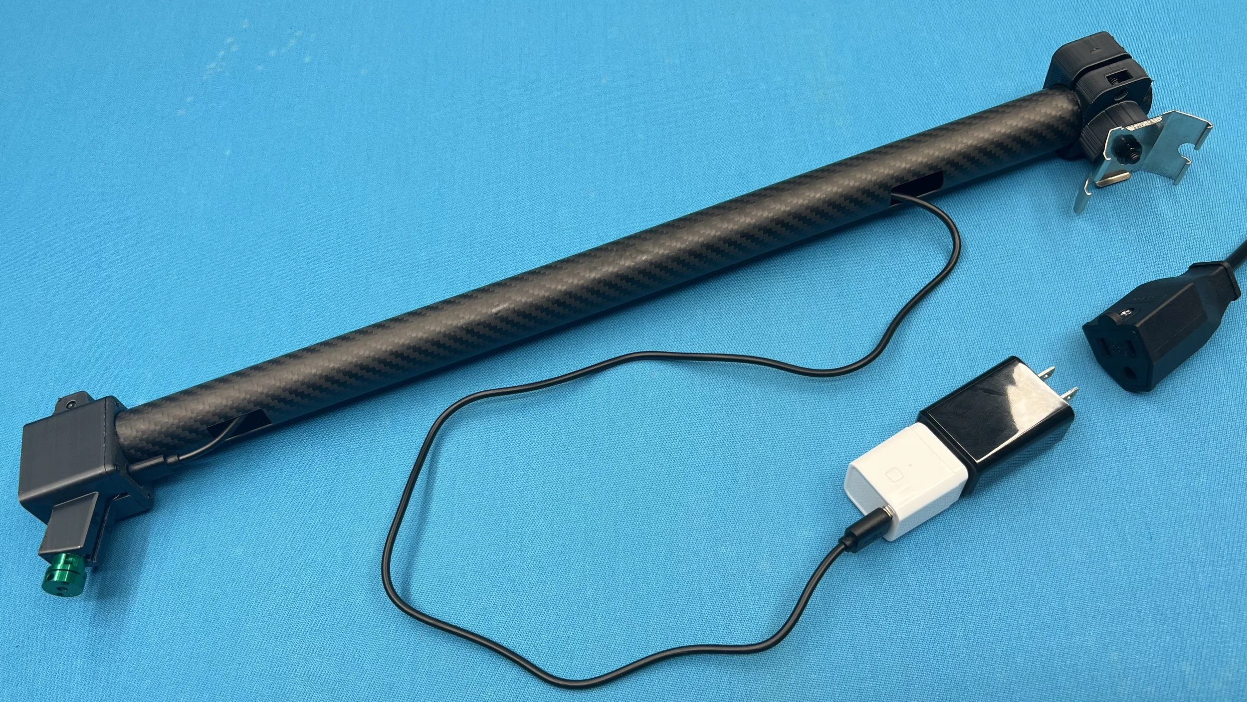
The PlaneView laser subassembly kit contains everything needed to connect, power, pair and calibrate the alignment device on your Arena Mark II platform. The “Laser Projection Head” unit is suspended above the center of the footstring “racking side” of the short end of the billiard table by a carbon fiber spine that houses a USB-C 5V DC power line plugged into the Arena AC Power tap. The C-clamp mount secures the spine to the fixture frame with a bracket and 2-part bracket-lock.
Using a twisting motion, slide the laser projection head onto one end of the spine. Use the M4-20mm screw and M4 nut to gently tighten the head to the tube (DO NOT over-tighten) so that the unit does not slide off the tube inadvertently.
Thread the USB power cable through the tube with the USB-C end protruding through the spine’s rectangular hole. Plug this into the Laser Projection Head. The USB-A end of the cable should extend toward the fixture side and exit through the opposite rectangular hole. Plug this into the Tuya USB WiFi Smart-switch device.
Directly connect the Tuya switch to the 5V 2A USB Power adapter and plug them via the Arena Power tap cable. Note: for better WiFi reception, you may need to arrange the Tuya switch just outside the Arena lid rather than inside the fixture using the wire management clips to hold down the exposed wires and smart device neatly on top of the fixture.
Attach a bracket to the center of the short segment nearest the footstring and attach the spine C-clamp to the bracket firmly using the M6-12mm screw and M6 nut. Slide the opposite end of the spine tube with a twisting motion into the C-clamp and adjust so that the laser and holes are pointing towards the table. It may help to remove one or both parts of the bracket-lock to shift the position of the bracket. Gently slide two laser shields (thin-side first). These limiters will be utilized during the final calibration to limit the laser line by cutting off the extent of the laser projection.
Adjust the direction of the laser beam on the table by rotating the knob on the head of the laser itself. Then adjust the spine by rotating the spine slightly and shifting the bracket position so that the beam travels through the second diamonds of both short rails. Once the laser is aligned, tighten the bracket-lock base to the bracket-lock plate (M4-12mm screw) and tighten the C-clamp around the spine.


